-
External power options:
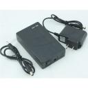
People will tell you to spend far too much on battery plates, or branded solutions. Here's what I've been using with my GH2's: a self-contained li-poly battery back from Ebay, eg. www.ebay.co.uk/itm/331257847808
Available in various mah ratings, mine's 6800mah. Cost around £16 (~$27 USD) and powers my dual-body GH2 rig and controller pretty much all day. It even has a switch, so you don't need anything else to simul-power (well, the battery is 12V so I use a voltage regulator for the correct GH2 voltage, but the Pocket takes 12V).
 $T2eC16Z,!zoE9s5ngNEvBRkF2+2kow~~60_57[1].JPG600 x 600 - 28K
 -
Wonderful, thank you for all of this.
With one camera inverted and no connectors we are able to achieve a ~73mm IO. With right angle mini HDMI and right angle LANC we are in the 92 - 93mm range. For closer IOs we put together a little prism rig that works pretty well but not exactly one's first choice.
Our further button pushing produced the following semi-trustworthy results:
The lens release apparatus does not seem to reset the internal clock with either automatic or manual lenses. Pushing that release mechanism does reset focus.
However, hitting the record button returns the camera to ready status from playback and this action does reset the internal clock. I momentarily thought this could be the golden fleece in that a simultaneous record command (which is possible from our Applied Logic board) should reset the clocks at the same moment. Practice, unfortunately, does not bear out the theory.
I am able to synchronously start the cameras with the power on buttons and get a (purported) 5ms sync between the two cameras roughly 50% of attempts - not awful, but, once again, not one's first choice.
I should say that these modest tests were done with the led readouts of the Applied Logic board which is likely not as reliable as Peter's CRT sync testing but it does, at least, tell one when there has been a resetting of the internal clock.
I have not yet, but will attempt the synchronous applying of power to the cameras to see if power on actually starts the internal clocks.
-
Inverting one camera shouldn't really work due to rolling shutter, which would skew in opposite directions. Have you found that in practice? I've studied the teardown screenshots, and if you're willing to really hardware-mod the cams, you could probably rotate the sensors 90 degrees - then you could use both bodies vertically, with the closest interaxials, without any downsides (even both screens would be visible - see pic).
Or, if you can extend the sensor ribbon cable, you could mount the sensors (with their lens mounts) completely seperately, as close together as possible (I'd worry about compromising the signal integrities, but it might work).
I also use right-angle connectors on my GH2's, but I'm still limited to ~140mm SBS, which is pretty hyper (but OK when observing a minimum distance from the lens). So 70-95mm would be nice for me.
When you say 'prism rig', are you actually using a prism? Or is is a beamsplitter? I'm planning to build a beamsplitter 'macro box' for the same reason (and to actually shoot macros).
re. buttons, the 'record from playback mode' sounds promising. Are the cameras actively playing back a clip? If yes, they may be busy and so not responding quickly enough to the record cmd, causing random delays. If they're not playing back, then I wonder what would cause the delay - maybe the LANC implementation just isn't polled (monitored) frequently enough. In that case, physically hard-wiring the record buttons to an external trigger might fix that (unless the record buttons are also polled slowly).
I'm most excited right now about the possibility of a hardware clock hack. I wasn't expecting the disassembly to be this easy, or the board to be this open. Other manufacturers like to remove IC markings, or hide one IC under another, so you can't even get at the clock. Or the clock might be embedded in a custom chip. As BMD is small, they seem to have avoided all that and gone for a relatively simple and open design. We just need the right eyes on the pics (my electronics experience is limited, though I might do the mod if it looks promising) - the prize is perfect permanent sync!
 rotate_sensors.jpg553 x 542 - 125K
 -
We could also use high-resolution pics of the boards that clearly show every marking. I've not been able to find any other teardowns. Is anybody willing to open a Pocket and take good shots from multiple angles? Most important is the front of the board (that wouldn't require disconnecting any cables).
I won't do it with mine when they come (could be longer than 2 weeks, my supplier can't get stock) for a while, as I'd first want to be sure that the sensors and everything are perfect before voiding the warranty.
-
Regarding Hardware Hack and the Chip you linked to, http://www.xilinx.com/support/documentation/user_guides/ug385.pdf
It looks like 5 pins could be of interest.MGTREFCLK0/1P Input Positive differential reference clock.
MGTREFCLK0/1N Input Negative differential reference clock.
CCLK Input/ Output Configuration clock. Output in Master mode or input in Slave mode.
USERCCLK Input Optional user configuration clock input in Master modes. GCLK Input These clock pins connect to global clock buffers.That said, I still believe an answer will be with a cheap HDMI repeater/splitter/switch.
For Example http://www.ebay.com.au/itm/Full-HD-1x2-Port-HDMI-Splitter-Amplifier-Repeater-3D-1080p-Female-HOT-2014-EG-/271546643718?pt=AU_Television_Accessories&hash=item3f3970f506&_uhb=1
or
http://www.ebay.com.au/itm/NEW-40M-Mini-HDMI-Joiner-Repeater-Extender-1080p-Amplifier-Booster-130FT-Black-/400710795942?pt=AU_Television_Accessories&hash=item5d4c3982a6&_uhb=1Inside that box will likely be a single device, whose primary purpose is to raise the levels of the signal ... including the sync. And it's highly likely that the clock pulse will be available on a single pin.
The first device will give you the split as well, if you can find a 2 x HDMI frame packer.
Feed the two sync pulses into a pic/arduino/avr and measure the difference, display on an 16x2 LCD Get one and have a look ... Initially use one of these to locate the signal http://www.ebay.com.au/sch/i.html?_from=R40&_sacat=0&_nkw=pocket+oscilloscope&LH_PrefLoc=1&_sop=15
This device http://www.ebay.com.au/itm/New-3-2-LCD-200KHz-Mini-Pocket-Oscilloscope-ARM-Dual-Channel-D602-/281318361379?pt=BI_Oscilloscopes&hash=item417fe18923&_uhb=1 will function as the sync reader and display the offset of any two sync pulses ... no hardware to build ... open repeaters ... connect oscilloscope inputs ... your measuring sync in real time ... offsetting startup will require AVR programming/hardware.
Using a repeater is not something I have done ... but if you google syncing two projectors for screening 3D, you will find references. The second chip I linked to is one that was documented.
-
@kavadni thanks, I will take a look at the chip doc tomorrow.
However we're mixing up two ideas - extracting sync from HDMI for measurement is another (less important) issue. What I'd really like is to be able to clone the master clock (or capture clock) on the circuit board of one body, out to a wire to the other body, to slave that body to it. Then frame capture (and maybe the entire digital systems) would be in perfect sync permanently (no need to measure sync anymore! : ).
I know people have done this with other cameras over the years. It involves find the crystal(s)/oscillators, running are wire out with the clock signal (may require some kind of buffering), and wiring it into the other body to replace its own clock. Then one body's timing is totally slaved to the other.
(you could also put the original clock on a little switch, then the camera could be toggled from independent to slave, without opening it up again).
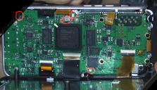
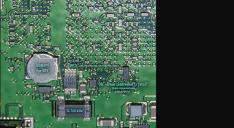
I don't have enough electronics experience to do that, I'm not even sure where the clocks are (although the silver pieces near each large chip, eg. above the FPGA, are the obvious candidates - see pic).
 poss_clocks.jpg1671 x 960 - 1019K
 -
What I'd really like is to be able to clone the master clock (or capture clock) on the circuit board of one body, out to a wire to the other body, to slave that body to it.
I think is a good idea .. that said to get to that state ... you will need to be able to isolate and measure it to achieve that state.
-
I approached BMD support for hardware mod or firmware addition help, but it looks like we're on our own:
"I am sorry to say that we cannot provide any information about the hardware for the Pocket Camera or provide support for modifying the hardware for custom developments.
We also do not do custom firmware development. Any features that are introduced into the product would be part of our development roadmap and long term plans. Currently, there are no plans to develop 3D for this camera as it was not designed with 3D shooting in mind, so I do not expect that this is something we would introduce in the future."
-
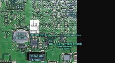
I've been reading up on crystals (http://en.wikipedia.org/wiki/Crystal_oscillator), and I found one! Crystals or Oscillators (both used as digital clock sources) are usually marked Y (for a crystal) or G (for an oscillator using some other material) on the circuit board (look for the black labels next to components). IEC standard may also use B.
U and MC on the other hand are various microprocessors.
That seems to rule out at least two of the silver components on the top half, marked MC1 or U.. (see pic) - I can't see a label for the one with the question mark, but it looks identical to the one on the far left, so it's probably also out.
That leaves the crystal on the bottom marked Y2 : ). It seems to be timing the processor right above it. This could be the master cock!
EDIT: as it's labelled "2" there should be a Y1 somewhere too ... can anyone see it?
 poss_clocks2.jpg1088 x 640 - 256K
 poss_clocks2_200%.jpg2176 x 1280 - 662K
 -
@David_Wilson, I'd love to hear if simul-powering does actually sync. When you can, please also try leaving a body running, and power-cycling the other a couple of times - does it stay in sync?
-
... Y1 is on the back, and seems to be a substantial & more easily solderable component (see pic). The only visual reference I can find to black-cased crystals are eg. this SMT crystal oscillator: http://mistermobiless.blogspot.co.uk/2010/12/oscillators.html
Considering the prominence of the component, it suggests high-accuracy - I'd guess this is the master/sensor clock!
 crystal Y1.jpg2575 x 1429 - 1M
 -
I understand that flipping one camera is likely not ideal, but In our experience/shooting style, miss-match of rolling shutter artifacts have not been a problem which isn't to say, of course, that it couldn't rear it's ugly head. We tend to shoot quite conservatively in terms of motion.
The groups efforts at hardware modification are truly inspiring. Such practices are neither foreign nor frightening to us, but, at this moment, our situation is such that we are withing 7 weeks of departing for 7 weeks shooting in Siberia and we need to go for the jugular (so to speak). Our backup for higher motion situations (we are going to be travelling on a lot of trains after all) is a pair of backbone modified GoPro 3+s with the new GoPro sync system which seem to work beautifully. There are trade offs for each and every system, in our modest arsenal at least. (We actually have a Epic/Scarlet combo but that trade off is clearly size and weight - not in the cards for these, our upcoming efforts.)
I will try today to get into the shop and do the simul-powering test gl suggests.
Endless thanks for everyone's truly excellent work.
-
Just remembered gl's question about the prism rig - which is nothing more that a set of 4 right angle prisms arranged, really, in a Wheatstone configuration which brings the BMPCCs down to about a 3mm IO. We have, as well, built a beamsplitter rig but the consensus at the moment is that it is a bit too delicate and figity for the rigors of travel.
Going to try to get in to do the simul-powering test now...
-
@David_Wilson, sounds exciting. Also sounds like my style of shooting, outdoors / documentary style, carrying everything yourself. I often get away with minor sync issues, but even slightly bad sync does fall apart for me. eg when a bird flies across the frame, with water reflections, moving foliage, snow etc. My eyes are really sensitive to it now, and while the audience may not be, they will experience it as unpleasant. Considering how easily many people are turned off 3D, you don't want to give them another excuse.
I also don't usually shoot anything where rolling shutter matters, though sometimes (eg. from trains as you mentioned). But anybody shooting action or hand-held (with deliberate movement) will want to avoid reversing cams and really needs good sync.
Have you ever hacked a crystal before? I'm not sure what I'm doing yet, though I feel like I'm getting close to something. I suspect that to clone the clock via a wire to the other body, it needs to be amplified/buffered somehow so that it gives the same electrical performance as at the source. Then it might just be as simple as unsoldering the clock on the other body, and wiring in the cable in its place. Anybody have experience?
Look forward to your powering results. These collabs are fun!
-
Mmmmm... OK, I tried simul-powering but maybe I'm not thinking this through very well. I did what I think is a simul-powering of both cameras by plugging the power adapters into a multi-outlet strip and providing power to both cameras at the same time. It seems to me, however, that if I need to start the cameras after powering them, even if the clock began to run when the camera received power, my starting of the cameras would override any existing clock start. At any rate, when leaving one camera running, and power-cycling the other the cameras do not stay in sync.
We, sadly, do not have any experience hacking a crystal. Not having any idea what I'm talking about, one possibility might be to have an external crystal that sends a sync signal to both cameras.
I too have become hyper aware of stereo miss shutter-sync and miss-alignment. I was astonished that in Werner Herzog 's utterly wonderful Cave of Forgotten Dreams, all of the non SI2K footage had what I experienced as truly bad shutter-sync problems but no one else seemed to notice or even mention it.
In our current planning, we will be taking a Helix gimbal on which we would like to mount the BMPCCs. Tests we've done so far don't seem to exhibit miss-matched rolling shutter artifacts at all but we clearly need to keep testing.
-
Thanks for the tests. I think it's probably safer though to power the bodies from a single PSU or battery, using a DC splitter cable. Otherwise there may be some differences with the PSUs getting to a stable voltage, giving us another random variable (maybe it's not significant but better to avoid it). Do you have a splitter cable to try?
As the cameras don't seem to stay in sync after power cycling one, powering up does seem to reset the capture clock. If so, supplying simul-power (without getting the cams to power up simultaneously) doesn't work : (. On the other hand, if we find a way to power both up simultaneously, they might be in sync right? (unless something else resets the clocks by the time you record)?
re. external crystal, my hunch is that it's easier to clone one. It will already be in spec/correctly designed (crystals seem to rely on external capacitors for fine tuning). Or put another way, cloning an external one to two bodies could be twice the work of just cloning one. The other advantage is that one body will always stay fully functional, so you can use it for 2D inbetween 3D shoots too (useful to me as they'd be my only cams).
Gimbal sounds cool, that sort of stuff is way out of my price range (I'm doing these things on a shoestring). Interested in your experiences though.
re. Cave of Forgotten Dreams, I haven't seen it, the missyncs sound sound bad though. I did once see that Chinese erotic flic that was super-succesful over there, I forget the name. But that had a couple of really nasty shots, eg. a greenscreen window where the inserted background was in pseudo. Obviously terrible but it got through somehow.
-
I don't have a power splitting cable to these. I should probably think about getting one. I'm pretty sure, however, that turning on the camera does reset the sync clock.
I hear you about the crystals and especially not disabling both cameras for other shooting.
Life in these parts is typically lived on the shortest of shoestrings as well. On occasion we get lucky - this project got funded which gives us some true breathing room for a change.
Actually, I would truly recommend Cave of Forgotten Dreams if you ever have a chance to see in in 3D. The sections where they took a matched pair of fully synced SI2Ks into the cave of completely beautiful 32,000 year old paintings is some of the best use of 3D I've ever seen. Other parts of the film where they shot with unsynced handy-cams of some flavor have some pretty uncomfortable shutter sync problems.
I'm very hopeful about your thoughts for slaving one camera sync to the other even if we don't get there in time for this project of ours. Having a truly reliable, high quality stereo camera system with possibilities for IO variation etc. would be a long time dream come true. The closest I ever came was a pair of synced Nizo S8 cameras many decades ago.
-
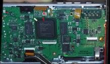
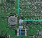
OK, these are my best guesses about the clocks so far:
RTC (time/date with battery backup): DS1307 (not marked 'DS', but pins make sense): http://datasheets.maximintegrated.com/en/ds/DS1307.pdf
Y1: 32.768 kHz crystal (for RTC, maybe also drives the rest). Looks unmarked, which would match this one visually (and specs match RTC requirements): http://www.digikey.co.uk/product-detail/en/CM200S-32.768KDZB-UT/300-8317-6-ND/862955
OX: Oven controlled crystal? Need better pic.
Sound right?
The field of pins top/right is the FPGA, so a clock should hit its pin(s) somewhere. @kavadni, can you try to trace the sync pins you found to one of these chips? Didn't get time today.
 clocks_best_guesses.jpg1708 x 935 - 427K
 -
FGPA details:
Family  :  Spartan-6
 Type    :  FGG484
 Device  :  LX75  (280 avail. User IOs, 140 Differential Pairs)
 Package :  BGA
 Size    :  23x23mm
 Max IOs :  338
 Pitch   :  1.00mm
If someone can take a look, details on how it's clocked & pin locations: http://www.xilinx.com/support/documentation/user_guides/ug382.pdf What I'm looking for is which pin(s) on the FPGA are receiving global clock(s), and matching them to the rear board picture (full version: http://www.personal-view.com/talks/discussion/comment/176953#Comment_176953), so we can trace the clock source.
I've updated my best-guess picture a little (below), but I'm having a hard time following the traces. Also am I right in assuming that the large darker patches in various places on the circuit are ground planes?
 clocks_best_guesses2.jpg1970 x 1078 - 488K
 clocks_best_guesses2 (no overlays).jpg2627 x 1438 - 682K
 -
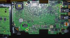
Stared at this some more, my latest guess:
- according to the SMD Codebook (http://www.marsport.org.uk/smd), OX (although they list a lower-case 'x') may be these Schottky diodes: http://www.avagotech.com/pages/en/rf_microwave/diodes/schottky/hsms-280r ). The 6 pin package matches (although there is a weird shadow on the component on the screencap that makes it look like a 4 pin device, I think it's 6?).
(the idea is that there isn't enough space on many SMD components to write proper device codes, so often you just get some cryptic 2 or 3 letters).
If so, the (assumed) 32kHz crystal seems the primary clock source:
- it's feeding the (assumed) DS1307 RTC (hence the 32kHz assumption).
- the RTC can optionally output a digital clock. Its pin is markedly soldered, and seems to lead towards the FPGA pins. So this probably clocks the FPGA digitally:
"Pin 7: SQW/OUT Square Wave/Output Driver. When enabled, the SQWE bit set to 1, the SQW/OUT pin outputs one of four square-wave frequencies (1Hz, 4kHz, 8kHz, 32kHz). The SQW/OUT pin is open drain and requires an external pullup resistor. SQW/OUT operates with either VCC or VBAT applied. The pullup voltage can be up to 5.5V regardless of the voltage on VCC. If not used, this pin can be left floating."
If true, then:
- it seems likely that it also (directly or indirectly) clocks the sensor. So rather than hack into the crystal itself (which is capacitance sensitive), the approach might be to cut the RTC's clock out pin, and insert the cloned clock from the other body's RTC there instead.
(it shouldn't matter that the RTC's themselves aren't synced, as they only do low-precision time/date keeping)
- the DS1307 datasheet says that its clock output is optional, and defaults to off on powerup. So something else must be programming it to enable the clock. Maybe the processor with its own crystal (Y2) on the front is in charge of booting the rest of the system? This would make sense, it would be scanning the power button when everything else is shut down, and then booting the FPGA by enabling the RTC clock output.
Cutting & soldering the RTC pin should be easier than trying to mess with SMD components, seems doable (if I'm right).
Even if all that works, I wonder what happens if one body boots faster than the other. So if the slave gets the clock, but can't use it yet, they may still start out of sync. There would be no drift, but there would be a permanent sync offset.
Thoughts?
 clocks_best_guesses3.jpg1190 x 1078 - 381K
 -
@David_Wilson, you said earlier that pressing record when in playback mode is resetting the clocks, but that the bodies weren't in sync afterwards anyway. Were you playing back a clip at that point, or where you paused/stopped?
If you were playing, the cameras may have been too busy to react quickly enough to the record cmd. If so, please try when they aren't doing anything.
-
re. splitting power, if you don't want to make your own cables, 2.1mm DC splitter cables are common on Ebay: http://www.ebay.co.uk/sch/i.html?_odkw=%220.7mm%22+dc&_osacat=0&_from=R40&LH_PrefLoc=2&_trksid=p2045573.m570.l1313.TR12.TRC2.A0.H0.X2.1mm+dc+splitter&_nkw=2.1mm+dc+splitter&_sacat=0
(my Ebay batteries also use 2.1mm).You can get various 0.7mm adapters for them: http://www.ebay.co.uk/sch/i.html?_odkw=%220.7mm%22+dc+splitter&_osacat=0&_from=R40&LH_PrefLoc=2&_trksid=p2045573.m570.l1313.TR0.TRC0.H0.X%220.7mm%22+dc+&_nkw=%220.7mm%22+dc+&_sacat=0
I think I'll go with adapters, as 2.1mm cables/sockets/plugs are much easier to get and replace if one goes bad.
EDIT: of course we want a right-angle plug to get the closest interaxials. This DIY cable from China is the cheapest solution: http://www.ebay.com/itm/251583079697 (they don't ship to England though for some reason - maybe just a mistake, I've messaged them).
Or you can buy ready-made ones from eg. Lanparte (expensive though): http://www.ebay.com/sch/i.html?_from=R40&_sacat=0&_sop=15&_nkw=Lanparte+BMPCC+DC&rt=nc&LH_PrefLoc=2
-
Pocket power draw: 6.8W (according to BMD) = 0.57A @ 12V
So with my 6800mah battery & 2 bodies = theoretical 6 hours runtime (ballpark). Obviously extra power for stabilised lenses & other gadgets (eg. 12V HDMI monitors) need to be factored in, pretty decent though.
Do Pockets need a battery installed to use external power?
-
"If so, please try when they aren't doing anything." Will do.


Howdy, Stranger!
It looks like you're new here. If you want to get involved, click one of these buttons!
Categories
- Topics List23,992
- Blog5,725
- General and News1,354
- Hacks and Patches1,153
- ↳ Top Settings33
- ↳ Beginners256
- ↳ Archives402
- ↳ Hacks News and Development56
- Cameras2,367
- ↳ Panasonic995
- ↳ Canon118
- ↳ Sony156
- ↳ Nikon96
- ↳ Pentax and Samsung70
- ↳ Olympus and Fujifilm101
- ↳ Compacts and Camcorders300
- ↳ Smartphones for video97
- ↳ Pro Video Cameras191
- ↳ BlackMagic and other raw cameras116
- Skill1,960
- ↳ Business and distribution66
- ↳ Preparation, scripts and legal38
- ↳ Art149
- ↳ Import, Convert, Exporting291
- ↳ Editors191
- ↳ Effects and stunts115
- ↳ Color grading197
- ↳ Sound and Music280
- ↳ Lighting96
- ↳ Software and storage tips266
- Gear5,420
- ↳ Filters, Adapters, Matte boxes344
- ↳ Lenses1,582
- ↳ Follow focus and gears93
- ↳ Sound499
- ↳ Lighting gear314
- ↳ Camera movement230
- ↳ Gimbals and copters302
- ↳ Rigs and related stuff273
- ↳ Power solutions83
- ↳ Monitors and viewfinders340
- ↳ Tripods and fluid heads139
- ↳ Storage286
- ↳ Computers and studio gear560
- ↳ VR and 3D248
- Showcase1,859
- Marketplace2,834
- Offtopic1,320
Tags in Topic
- camera 247
- rig 106
- cinema 73
- bmpcc 61
- 3d 60
- pocket 26
- sync 12
- synchronization 3
- stereoscopic 3


