It allows to keep PV going, with more focus towards AI, but keeping be one of the few truly independent places.
-
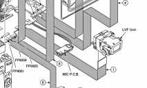
As GH-2s get used and misused, a number of unrepairable items and units will start to accumulate in repair shops. I was taking a look through the repair manual to see if it would be possible to remove the LVF or the LCD and re-locate it elsewhere; (for me, to the side of the lens as with a shoulder-mounted ENG camera). This would be effectively replicating a bench-testing setup but requiring a separate housing for the viewfinder outside the existing camera body. Extension cables exist, like the Part No RFKZ0477 which connects the EVF further away (on the bench top) to the circuit board , for testing purposes. A similar cable may exist for the LCD screen.
Well, this mod looks at first to be doable by the tech savvy or foolhardy. (!) CARE! viewfinder screens can carry high voltages!! [Edit 18 May] Added picture: for some of us it is highly desirable to have a camera truly on the shoulder with the sensor-plane rotating on the axis of the operator's body. A re-located eyepiece can enable this.
Cost: Longer ribbon cable $60. Electronic work: Zero, except perhaps encasing the cable in shielding and insulation. Main skills needed: Design, care with tiny screws, safety, maybe cutting & bending plastic, adhesives.


 lcd2.png490 x 700 - 55K
 lcdHinge.png511 x 400 - 39K
 lvf.png679 x 408 - 160K
 cameraman.png505 x 543 - 148K
 -
I did mod a lot with my hvx-100 and XH-A1. Added a tube based b/W, viewvinder mountable on the hotshoe getting the video signal and tally signal from the cameras 3,5mm microphone Jack.
Thought of using the GH2´s bezel to permanently attach a tube with magnifier. Also knowing the circuitry of the mic´s amplifier would be helpful. Could you help out? All the best, Frame
-
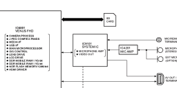
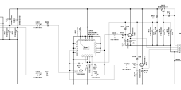
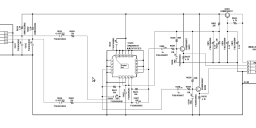
@Frame The Mic/ext mic input is via IC4201 (20 pins) which has its own PCB. Maybe you can find out more about the IC4201's pin-outs. Sorry, I haven't opened up my GH2 to look at that IC. Maybe you can look up the GH2 photos to see what's written on the IC. [Edit 19 May]: larger diagrams added.
 mic.png848 x 338 - 44K
 mic_PCB_LARGER.png1215 x 515 - 32K
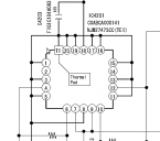
 IC4201.png484 x 428 - 13K
 -
I've been looking for a way to use sound-input as well as remote start-stop. As the 2,5mm jack does not allow for both, I wanted to see if I can replace the internal mic with external connectors.
I guess the best option is to drill a small hole in the top-cover, opposite of the 'open' lock for the flash. Then you could take the white connector out of the mic-PBC and take it outside through that hole. If it's possible to get a female connector one could make a small break-out box with 2x XLR on top of the hot-shoe. That way it would be easiest to restore it to it's original.
@Roberto Here are the pictures of the mic again. Where did you get the repair manual and do you do repairs yourself?
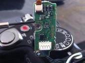
 IMG_0343.JPG2592 x 1936 - 1M
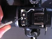
 IMG_0344.JPG2592 x 1936 - 2M
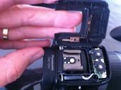
 IMG_0345.JPG2592 x 1936 - 2M
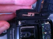
 IMG_0346.JPG2592 x 1936 - 2M
 -
Looks like you've got the experimenter's bug! Please do be careful - think of your own safety first.
Always remember to discharge the FLASH terminals before poking around.
Next, try not to fry anything in the camera: take a good look at any PCB to make sure you're only messing with analogue circuitry, not logical, that way you won't find the camera defaulting into a "take me to a Panasonic service centre" mode.
Manuals, service-only parts and testing tools are available to licensed repairers. You just might find a friendly independent repairer in a small town ;-).
That said, to my eyes, (not a Panasonic repairer), what you're proposing looks do-able and I am looking forward to your results.
-
Thanks for your help. Updated pics in previous post. As I said, a look inside may reveal a proprietary name on what Panasonic calls " IC4201" and just possibly more info on what this IC does. There may be unused functions, we could use alternative ICs, etc.
If the camera is still open, can you take a closer look at the mic PCB and see what's written on the main IC? (I think it's the blurry pic below).
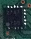
 icphoto.jpg240 x 304 - 26K
 -
@svart that would be great! would be good to find if there is any sort of phantom power and the exact input specs..
-
@DirkVoorhoeve, @Roberto: So the main IC you see in the pic is an NJM2747SCC, which is a generic quad opamp. The configuration is strange because they only use 2 of the 4 opamps in the package. If you look at the schematic on connector FP4201(right side), pin 1 is labeled as what I think says PW_REG4R8Y. It's still a bit hard to read though. Anyway, this looks like some kind of bias/low voltage phantom power as it goes through 3K3 resistors to ECM_LIN/ECM_RIN and is AC coupled(DC blocked) by C4201 and C4204. 4R8 would typically mean 4.8VDC. This would be enough for back electret mics but not true condenser mics. The NPN transistors Q4201 and Q4202 are common collector configurations, which is generally used as voltage buffers to drive low impedance loads and won't have much voltage gain. So in other words, the opamp does the gain and the BJTs do the driving.
Also: do NOT force 48V phantom into these inputs from an external source, there is no true overvoltage protection for the opamp, which is also fed from the 4.8V source and phantom could be forced back through the 3k3 resistors and into the IC.
-
@svart Tried to understand what you wrote, but I am afraid that I'll need to buy an 'electronics for dummies' book first. But to summarize the part that I think I understand: the ECM plug connects the two Electret Condenser Microphones to this PCB, and they get their power from the pin 1 of the MIC connector (right side of the diagram, bottom of my picture).
If I understand this correctly, do you think there a fixed amount of gain applied in the PCM and then later on inside the camera body again (selecting mic level 1, 2 or 3)?
Would it be possible to connect the output of my mixer directly to the MIC connector's pin 2, 3 and ground?
-
@DirkVoorhoeve, yes, that's essentially how the circuit connects to the electret mic elements. The mics connect to the connector on the left side, are gained and buffered and then go out to the rest of the circuit through the connector to the right.
This is all fixed gain on this board. There is no AGC(automatic gain control) in this circuit at all, so I expect the 3 steps of gain are done digitally, or done through an IC on another board before being digitized.
It's possible that you can connect your mixer! I'm not sure what kind of levels the MIC_RIN/MIC_LIN need to see though but that should be pretty easy to figure out. Just start low and work upwards. It looks like the most the opamps can do is around 3-4vpk-pk in this situation at full gain.
-
IC9101 to AV out!?
-
I was sort of hoping the op amp might be switchable to comparator mode; ie if it senses a line level it bypasses its pre-amp so you can just send your own pre-amp signal through the mic terminals.
My Sony engineer friend says camera pre-amps are crackly because they typically use cheap, power-saving chips - and that you'd really have to be a Panasonic engineer to know what cameras' sophisticated circuitry does. Until we get one to talk to, we'll have to limit any testing to, say, analogue trials with the mic PCB on its own on the bench top.
I certainly wouldn't subject a perfectly good GH2 to a smoke test.
-
@Roberto, the preamp circuit is pretty simple. I've done a fair bit of work designing audio circuits before. The NJM parts themselves are pretty clean. The problem comes with the amounts of gain needed, which will cause any impedance mismatch or unclean signal/power from the mics to become huge amounts of noise after amplification. This is compounded by the unfortunate fact that audio is almost always an afterthought in cameras. I think the hissy/noisy nature of the audio in most of these cameras comes from the electret microphones. These are very good devices for fidelity and sensitivity, but are generally noisy. I've done some designing using these mic elements for pro-audio use and they are capable of extremely good sound but are not usable for low signal levels. Good for drums and electric guitars. Not good for voiceovers or background mics.
Now, you can modify the electret mics to get better performance. The most prevalent one is called the "Linkwitz" mod, after the famous speaker designer who came up with the mod.
Scroll down to "microphone" section and check out some interesting modifications: http://www.linkwitzlab.com/sys_test.htm
http://www.mp3forkidz.com/mic/mod.html
This would change the way the mics work and a lot of testing would be needed, but it could improve the overall sound of the internal mics of the unit, possibly.
Here's what's actually in the mic: http://www.pitt.edu/~szekeres/mic/wm63.jpg
-
@svart Interesting!
I'm finding it hard to see what would happen if the wiring to the capsule's internal FET were changed as in Linkwitz WM-61A mod. It looks to me that the capsule case's earth output is on the +ve drain side of the FET (floating earth) to the mic PCB anyway. I'd really only feel safe changing to better capsules and testing analog output to avoid the GH2 sensing a difference and activating protective circuitry.
What did you have in mind?
@DirkVoorhoeve Did you happen to see if your GH2 uses one of the WM-61A or B capsules? and.. @gizmo
We were all saddened by your GH2 loss. It's been some time now and I hope you're coping. Are you ready to discuss the delicate matter of donating the mic PCB to science?
-
maybe a little off topic here, but I was wondering, especially to people who have access to schematics etc, what kind of signal does the remote input require. Is it passive input (switch on/off) or does it require some signal (which amplitude, pulse timings)?
The background idea is, can I use a portable mp3 player to send a specially crafted signal (e.g. generated in Audacity) in the remote input?
-
the main IC you see in the pic is an NJM2747SCC, which is a generic quad opamp. The configuration is strange because they only use 2 of the 4 opamps in the package. If you look at the schematic on connector FP4201(right side), pin 1 is labeled as what I think says PW_REG4R8Y. It's still a bit hard to read though. Anyway, this looks like some kind of bias/low voltage phantom power as it goes through 3K3 resistors to ECM_LIN/ECM_RIN and is AC coupled(DC blocked) by C4201 and C4204. 4R8 would typically mean 4.8VDC. This would be enough for back electret mics but not true condenser mics.
One thing which keeps going round in my mind is the small print in the manual of my 1981 Radio Shack condenser-mic 33-1080 "1-12V!" In the place of a single AA battery recommended I fitted two x 6V batteries of the same diameter - and got a totally different, 12V mic!
OK, it's a long-shot, brute-force solution, but do you have info into the voltage ratings for the IC and op-amp inputs?
-
Yes, the opamp is 2-14V and the inputs are up to the rail voltages. However, The mics and the opamp are powered from the same rail. The output of the opamp will scale with the supply voltage and you'll mismatch your A/D inputs. You'd end up having to attenuate the output of the opamp with a resistor divider network and you'll end up with the same level going into your A/D but with possibly more noise.
what you could do is hack in a divider network between the voltage rail and the opamp, but you'd have to be careful not to overload the inputs with a hotter mic output. It's something to investigate but I'm not sure it'll pay off.
-
Thanks for looking into it. It's a more comprehensive answer than I'd expected but still makes me want to try something on the bench.
BTW, I just saw this GH2 top assembly for auction, (new). I can't see if there's anything in there besides the switches, tho..
http://cgi.ebay.com.au/ws/eBayISAPI.dll?VISuperSize&item=280917397638
Howdy, Stranger!
It looks like you're new here. If you want to get involved, click one of these buttons!
Categories
- Topics List23,993
- Blog5,725
- General and News1,354
- Hacks and Patches1,153
- ↳ Top Settings33
- ↳ Beginners256
- ↳ Archives402
- ↳ Hacks News and Development56
- Cameras2,368
- ↳ Panasonic995
- ↳ Canon118
- ↳ Sony156
- ↳ Nikon96
- ↳ Pentax and Samsung70
- ↳ Olympus and Fujifilm102
- ↳ Compacts and Camcorders300
- ↳ Smartphones for video97
- ↳ Pro Video Cameras191
- ↳ BlackMagic and other raw cameras116
- Skill1,960
- ↳ Business and distribution66
- ↳ Preparation, scripts and legal38
- ↳ Art149
- ↳ Import, Convert, Exporting291
- ↳ Editors191
- ↳ Effects and stunts115
- ↳ Color grading197
- ↳ Sound and Music280
- ↳ Lighting96
- ↳ Software and storage tips266
- Gear5,420
- ↳ Filters, Adapters, Matte boxes344
- ↳ Lenses1,582
- ↳ Follow focus and gears93
- ↳ Sound499
- ↳ Lighting gear314
- ↳ Camera movement230
- ↳ Gimbals and copters302
- ↳ Rigs and related stuff273
- ↳ Power solutions83
- ↳ Monitors and viewfinders340
- ↳ Tripods and fluid heads139
- ↳ Storage286
- ↳ Computers and studio gear560
- ↳ VR and 3D248
- Showcase1,859
- Marketplace2,834
- Offtopic1,320


