StreamParser 2.6
StreamParser is a video file analyzer targeted to Panasonic G series DSLR’s. StreamParser is only compatible with AVC files (“xxx.MTS”). This document does not explain the meaning of standard MPEG Transport Stream and H.264 elements and flags; it is assumed that the user is familiar with those standards. Descriptions of such items are readily available on various Wiki’s on the Internet.
Installation
StreamParser is compatible with Microsoft Windows only. StreamParser installation consists of the following steps:
Before installing a new version of StreamParser previous versions should be uninstalled. This can be done by running uninstall from the Control Panel. The Control Panel name for StreamParser is “GH13 Stream Parser”.
Create a temporary folder for Installation. This can be located anywhere.
UnZip the contents of the “StreamParserInstall.zip” archive into the temporary folder.
Execute “Setup.exe” by double clicking on it. StreamParser requires the .NET runtime. If not present on your computer, the installation program will automatically download it from Microsoft.
After installation is complete StreamParser will be started. If everything appears OK the temporary installation folder can be deleted.
The Main StreamParser Application
Before opening files with StreamParser copy them to your computer’s hard disk. There are two ways to start a StreamParser session. Selecting “File>Open” from the menu will cause an entire video stream file to be opened and analyzed. Alternatively, one can select “File>Quick Test” which will only open and analyze the first ten seconds of a video stream file (by default; the number of seconds can be changed by selecting “Configuration>Configure Quick Test”). Large files can take a very long time to analyze and unless there is a specific need to analyze the entire file using “Quick Test” is advised.
StreamParser starts up in “Frames Mode”, which contains the most commonly used tools.
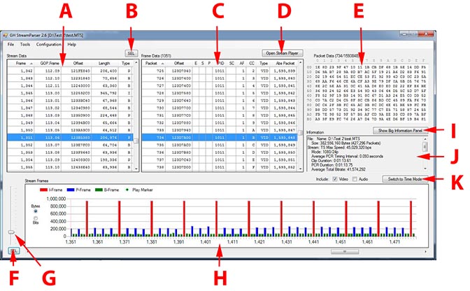
The StreamParser Frames Mode window consists of several components:
A. Stream Data panel. This breaks a stream down into frames. The first column shows frame number in display order. The GOP.Frame column shows the frame number in GOP.Frame format. Offset is the starting address of the frame in the MTS file. Length is the amount of data in the frame. Type indicates frame type (I, P, B, or A). Audio (A) frames are only shown if the “Include Audio” checkbox above the Stream Frames graph has been checked. Clicking on column headers will cause data to be sorted according to the selected column.
B. Sel. Pressing this synchronizes the Frame Data Panel with the Stream Frames graph. The first frame in the Stream Data Panel is set to the first frame shown in the Stream Frames graph.
C. Frame Data panel. This breaks down a frame selected in the Stream Data panel into Transport Stream (TS) packets. “Packet” shows the packet number relative to the beginning of the selected frame. “Offset” is the starting address of the packet in the MTS file. “E”, ”S”, and “P” are TS header flags. “PID” is the TS Packet ID. “SC”, “AF”, and “CC” are TS header flags. “Type” is the packet type – “VID” for video and “AUD” for audio. “Abs Packet” is the absolute packet number (i.e. relative to the beginning of the file). The number next to “Frame Data” is the selected frame number. Clicking on column headers will cause data to be sorted according to the selected column.
D. Pressing this will start up the media player. The media player is explained in more detail below.
E. Packet Data. This shows hex data for a packet selected in the Frame Data panel. The numbers next to “Packet Data” are Packet/Abs Packet number for the selected packet.
F. Similar to item B, above; except the first column in the Stream Frames graph is set to the selected frame in the Stream Data panel.
G. This slider determines how many columns are displayed in the Stream Frames graph; it is used to zoom the graph in or out.
H. The Stream Frames graph. Depending on which “Include” checkboxes are selected video, audio, or both frame types are plotted. The graph can be set to display frame size in bytes or bits.
I. Displays the contents of the Information panel (J) in a bigger window.
J. Information panel. This contains information about the Stream, the selected frame and packet.
K. This puts StreamParser into Time mode.
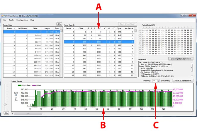
The StreamParser Time Mode window is similar to Frames Mode except instead of data being broken into frames it is divided by time slices. The components that differ from Frames Mode are:
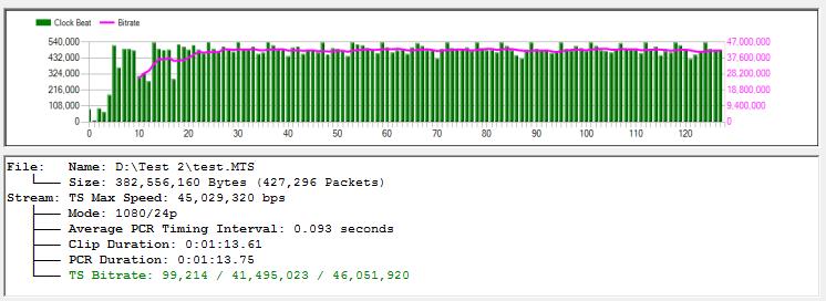
A. Frame Data. In Time Mode “frames” are actually time slices (typically 0.092-0.096 seconds). As such a time slice can contain different types of packets – video, audio, timing, parameter sets, etc… Unlike Frames Mode, Time Mode shows all packet types, not just video or audio.
B. The stream Frames graph shows the amount of data contained in each time slice.
C. This is a smoothing function (averaging) for the graph’s running bitrate line.
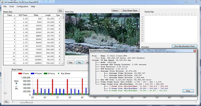
When “Open Stream Player” is pressed in Frames Mode a Windows Media Player window is opened in the Frame Data panel. The player can be detached and displayed in a separate window. When a stream is played a frame marker in the Stream Frames graph follows along. Also shown in the figure below is the window presented when “Show Big Information Panel” is pressed.
A short-form report suitable for posting on forums can be generated by selecting the “File>Generate Snapshot Report” menu item. The Snapshot Report can be saved as an image. Depending on StreamParser’s current operating mode (Frames or Time) one of two reports will be generated. The graph contained in the Snapshot Report is a copy of the currently displayed graph in the StreamParser main window.
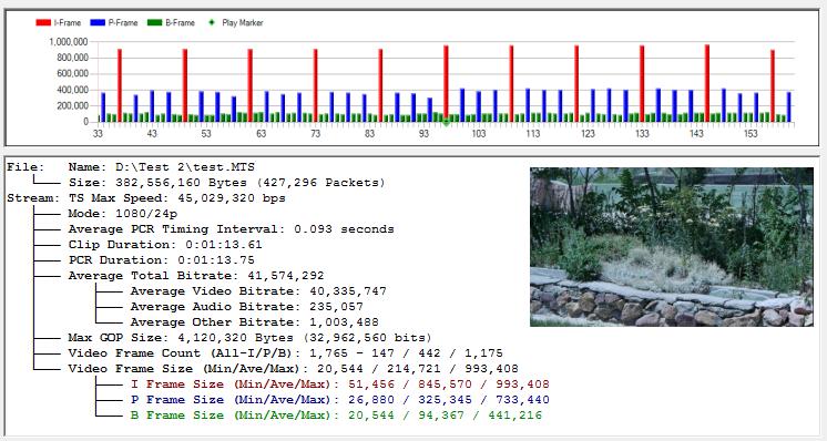 Note: Thumbnail is only shown when Stream Player is opened and not detached.
Additional miscellaneous menu options allow the user to check MTS file integrity (“Tools>Check Stream File”), select camera model (“Configuration> Camera”), select slow computer operation (“Configuration>Slow Computer”), and interpret hacked GH1 1080p25 files (“Configure>Interpret GH1 1080i60 as Hacked 1080p25”).
The JM-SP Decoder
StreamParser analyzes data at the Transport Stream (TS) level. The JM-SP decoder analyzes data at the H.264 Elementary Stream level, offering details about video encoding parameters and results. With the JM-SP decoder details are provided about quantization levels, scaling tables, skipped frames, and much more. The JM-SP decoder is based on the H.264 reference codec and as such is a good tool to test streams for validity.
Configuration
The JM-SP decoder is configured by clicking on the “Configuration>Configure JM-SP Decoder“menu item. The parameters are as follows:
Number of Frames to Decode. The default is 100. This determines how many frames will be decoded. If set to zero, all frames will be decoded.
Produce Trace File. This parameter configures the M-SP decoder to produce a trace file (“xxx.txt”) containing a great deal of H.264 header data. Normally, this is unchecked as there is not typically a need to examine such detail and the JM-SP decoder takes a long time to produce the file.
Force 32-bit Decoder. StreamParser is delivered with both 32 and 64-bit versions of the JM-SP decoder. This option forces the 32-bit decoder to be used even under 64-bit Windows.
Use
Before the JM-SP decoder can be run a Video Elementary Stream File (“xxx.264”) must be created by clicking on the “Tools>Create Elementary Stream File” menu item. The Elementary Stream File can also be used with other video analyzers and is normally much faster than using “MTS” files with analyzers such as Elecard’s StreamEye.
The JM-SP decoder is started by clicking on the “Decode Elementary Stream File (JM-SP Decoder)” menu item under “Tools”. After processing is complete a window is presented showing the decode log (which is also saved as “xxx.log”).
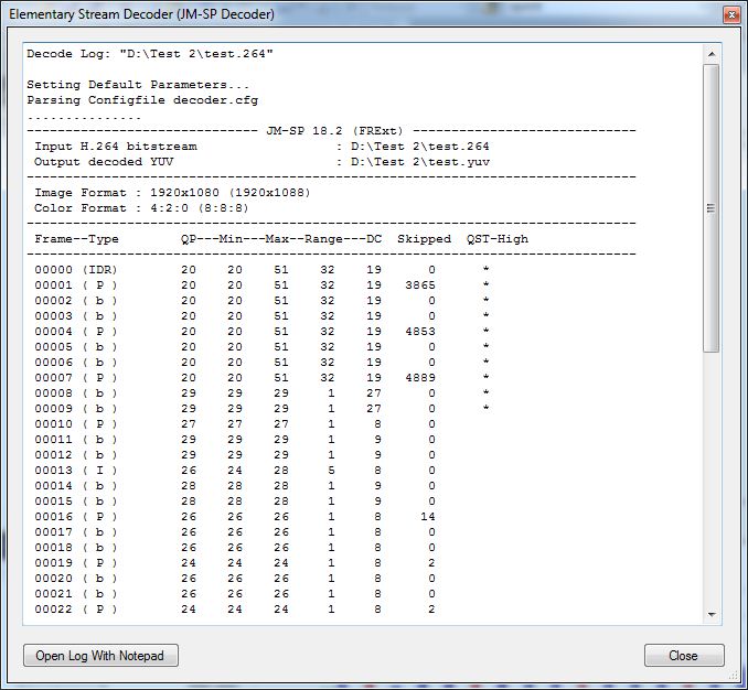
The log file contains quite a bit of useful data to help determine how well a video clip has been encoded. The items shown for each frame are:
Frame. This is the frame number in display order (the same as used in StreamParser).
Type. This indicates the frame type (IDR, I, P, B). Note that with interlaced video each displayed frame actually consists of two slices. For example, an interlaced I frame will show as an “I | P” frame because it is actually an I slice for the top half and a P slice for the bottom.
QP. This is the general QP setting for the entire slice (in the case of the GH2, the entire frame).
Min. This is the lowest QP setting used in any macroblock in the frame. The H.264 codec uses the frame QP setting as a base and each macroblock can modify the QP setting using an offset value unique to that macroblock.
Max. This is the highest QP setting used in any macroblock in the frame.
Range. This value is Max minus Min and shows the range for QP values. With test charts, a high range value indicates potential problems, as test charts (with high detail across the entire image) should be encoded with fairly consistent QP values for all macroblocks (a range of 5, or less). Real world subjects, on the other hand, can vary quite a bit. Even with real world subjects, however, a range of twenty or more is usually not good. A high value for Range will often indicate macroblocking in I frames (which are often propagated to subsequent B and P frames).
DC. This is the lowest effective QP value used for DC coefficients in the frame calculated by combining QP with the Quantization Scaling Matrix. A DC value below 4 is wasted in 8-bit codecs and just results in extra processing and no gain in quality. If values below 4 appear it is probably appropriate to raise the Q parameter value (or lower the AQ value) until no value under 4 appears.
Skipped. This is the number of skipped (not encoded) macroblocks in a frame. Low numbers are acceptable. High numbers with test charts (more than 50) indicate problems. The most common reason this happens is when the codec runs out of bandwidth and starts skipping frames to compensate. With real world subjects skipped frames occur normally in very low detail areas, such as sky. A high value for Skipped typically will indicate stuttering in motion, or macroblocking.
QST-High. If an asterisk appears here the codec has switched to fall-back mode to avoid crashing and is using very low detail (T4) Quantization Scaling Tables. This should rarely happen and only when panning across extremely detailed subjects using a high shutter speed.
Under normal circumstances the information contained in the JM-SP decoder log should be sufficient to evaluate how well video has been encoded and make changes to settings parameters in response. The trace feature can be turned to produce a trace file that contains much more information. The trace file, however, is fairly cryptic (being in H.264 header syntax) and can take a very long time to produce.


 Note: Thumbnail is only shown when Stream Player is opened and not detached.